International Telecommunication
International Standards
============================
Administrations and operating companies throughout the world carry on studies
of technical and other problems related to the inter-working of their respective
national telecommunication systems to provide a worldwide telecommunications
network. Two international committees exist for this purpose :
1) The International Telegraph and Telephone Consultative Committee (CCITT),
and
2) The International Radio Consultative Committee (CCIR).
They operate under the auspices of the International Telecommunication Union (ITU).
They promulgate their decisions in the form of Recommendations, which are published
by ITU. Generally, these Recommendations cover features of international circuits, but
where essential, they deal with relevant characteristics of the national systems which
may form part of international connections. This compendium collects, in condensed form ,
major Recommendations dealing with telephone, telegraph , and data-transmission circuits
and equipment.
https://www.itu.int/en/Pages/default.aspx
Recommendations of the CCITT
===================================
The CCITT develops new Recommendations, and updates existing ones, through
the activities of Study Groups, whose reports are acted on at Plenary Assemblies,
which meet at intervals f 3 or 4 years. The resulting Recommendations of the
Second Plenary Assembly, New Delhi, 1960, were published by the ITU in a number
of volumes, called collectively the Red Book. The subsequent study periods
culminated in the Third Plenary Assembly, Geneva, 1964 (Blue Book);
the Fourth Plenary Assembly, Mar del Plata, 1968 (White Book); and the
Fifth Plenary Assembly, Geneva, 1972 (Green Book). This compendium refers
to Green Book Recommendations, designated thus L (G.101), (H.31), (V.2), etc.
https://en.wikipedia.org/wiki/ITU-T
Recommendations of the CCIR
===================================
The CCIR also functions with Study Groups and Plenary Assemblies.
The Eleventh Plenary Assembly was held at Oslo in 1966, the
Twelfth Plenary Assembly at New Delhi in 1970, and the
Thirteenth Plenary Assembly at Geneva in 1974.
After each Plenary Assembly , the ITU publishes volumes which contain
the currently accepted Recommendations, including such
Recommendations of the Plenary Assemblies at London (1953),
Warsaw (1956), Los Angeles (1959), and Geneva (1963) which are
still effect. No color coding is used. This compendium deals with those
Recommendations which treat point-to-point radio relay systems.
A purpose of those Recommendations is to make the performance of
such systems compatible with metallic line systems which follow the
CCITT Recommendations. References to the CCIR Recommendations
are made this : (CCIR,391).
https://uia.org/s/or/en/1100018746
Zero-Relative-Level Points and Relative Levels
=====================================================
Many CCIT and CCIR Recommendations specify signal or noise levels at "a point
of zero relative level", or in dBm0 or pWp0, etc, where "0" (zero) stands for
"measured art or referred to a point of zero relative level".
1) 2-wire switching systems :
-------------------------------------------------------------------------
In 2-wire switching systems, the sending end terminals of a long-distance circuit
have long been considered to be at a point of zero relative level. The relative levels
of all other points are calculated from this reference point, as the algebraic sum of
all transmission losses and gains from it to the point in question. Any point in a circuit
with the same relative level as the sending terminals is a point of zero relative level,
which may be written 0 dBr (dB relative level). The American term for relative level is
transmission level. Thus : "Zero-transmission-level point" (0TLP).
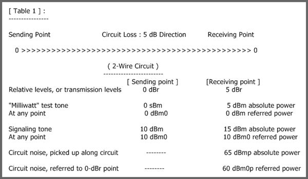
For convenience in comparing circuit noise performance, it is customary to convert
absolute noise measurements made at the receiving ends of circuits having various
relative levels, to absolute power levels, at a zero-relative-level point. For example,
50 dBmp of noise at a 7-dBr point would be reported as 43 dBm0p. Signaling-tone
levels are similarly expressed. For example, a tone introduced at a 3.5-dBr point
with an absolute power level of 18.5 dBm may be referred to as a 15-dBm0 signal.
The latter designation would apply to such a tone no matter where it appeared; the
"0" denotes that its level is referred to a point of zero relative level . (Refer to table 1).
Statistics of speed power, requirements for linearity and limiting, system loading
factors, cross-talk, and noise have become well known in terms of their values at
points of zero relative level. The proper performance of voice repeaters, carrier
terminal and line equipment, radio relay systems etc., depends on adherence to
the relative levels for which they were designed. Many relative levels associated
with such equipment have been standardized.
2) 4-Wire Switching Systems
==============================
In 4-wire switching systems, it is often considered desirable to handle speech and signaling at
lower values of absolute power through the switching equipment than is customary in 2-wire
systems. In 1964, the CCITT adopted a relative level of 3.5 dBr for the sending end of a 4-wire
circuit, at the "virtual" switching points. These are theoretical points; their exact location depends
on national practice , and the CCITT considers it unnecessary to define them. (In American
commercial system, 2 dBr is widely used).
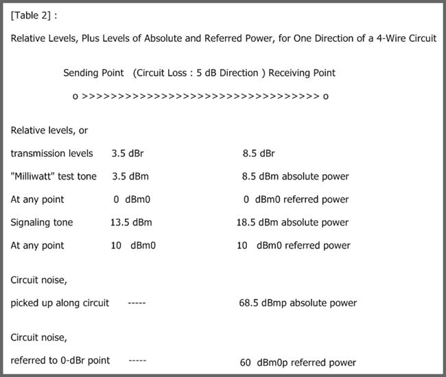
Therefore, to ensure that carrier and other transmission equipment will be subjected to the
same absolute speech and signaling power levels as in 2-wire systems, determination of
relative levels in 4-wire circuits must take into account the relative level of the virtual
switching points. In a 4-wire circuit, there may be no actual point of zero relative level.
Nevertheless, standards will continue to refer many requirements to a zero relative point.
(Refer to Table 2).
Currently, many transmission measurements are made with a standard 800 or 1000-hertz
test tone, with an absolute power of 1 milliwatt at a zero-relative-level point : a power of
0 dBm0. The actual level applied is adjusted to the relative level of the sending point. The
test-tone level in dBm will be numerically equal to the relative level in dBr at any point in the
circuit, but it is not proper to express relative levels in dBm, since dBm represents absolute
power levels. If the standard-test-tone power is ever changed to another value, such as
10 dBm0, as has been tentatively proposed, the distinction between relative levels and
test-tone levels will be more apparent.
Psophometric Noise and Power
========================
The CCITT calls a noise measuring set a "psophometer". A psophometer includes
a device for measuring power through a weighting network. For measurements
on commercial telephone circuits, a weighting characteristic is usedwhich results
in the objective instrument measurements approximately paralleling the results
of subjective tests with human observes using modern telephone sets. The CCITT
weighting characteristic for commercial circuits is nominally identical with the
American F1A line weighting. Psophometric noise power may be expressed in
dBm0 "psophometrically weighted", or dBm0p. The conventional conversion
equation used between dBm0p and dBa0 (F1A) is
dBm0p = dBa0-84
Psophometric Weighting for Commercial Telephone Circuits :
-------------------------------------------------------------------------------
Frequency (hertz) Level (dB)
100 -41.0
150 -29.0
200 -21.0
250 -15.0
300 -10.6
400 - 6.3
500 - 3.6
600 - 2.0
700 - 0.9
800 0.0
900 + 0.6
1000 + 1.0
1100 + 0.6
1200 0.0
1350 - 0.65
1500 - 1.30
1750 - 2.22
2000 - 3.00
2250 - 3.60
2500 - 4.20
2750 - 4.87
3000 - 5.60
3500 - 8.5
4000 - 15.0
4200 - 18.7
4500 - 25.0
4700 - 29.4
5000 - 36.0
Psophometric Weighting Factor
====================================
If uniform-spectrum random noise is measured in a 3.1-kilohertz band with
a flat attenuation/frequency characteristic, the noise level must be reduced
by 2.5 decibels to obtain the psophometric power level. For another
bandwidth B, the weighting factor will be equal to :
2.5+10 log10 (B/3.1) decibels.
When B=4 kilohertz, for example, this gives a weighting factor of 3.6 decibels.
Psophometric Power
=========================
Where power addition of noise can be assured, it has been found convenient for
calculations and design of international circuits to use the concept of
"psophometric power".
psophometric power = (psophometric voltage)2/600
= (psophometric emf)2/(4x600)
A convenient unit is the picowatt (pW) = 10-12 watt, so that
psophometric power in pW = (psophometric voltage in mV)2/0.0024
Conventional Telephone Signal
====================================
For the calculation or measurement of cross-talk noise between adjacent
channels, of the balance return loss for echo, and generally speaking ,
when it is desired to simulate the speech currents transmitted by a
telephone channel, the CCITT recommends the use of a conventional
telephone signal. This signal may be produced by passing the output of
a generator of a uniform-spectrum random noise signal ("white noise")
through a weighting network with a characteristic as shown in Fig.1.
The amount of this signal that appears in another circuit because of
cross-talk , etc., is measured with a psophometer or weighted-noise
measuring set, with standard psophometric weighting for commercial
telephone circuits.

Telephone Circuit Loading
===============================
To simplify calculations when designing carrier systems on cables or radio links,
the CCITT has adopted a conventional value to represent the mean absolute
power level , at a point of zero relative level, of the speech-plus-signaling
currents, etc., transmitted over a telephone channel in one direction of
transmission during the busy hour, which is -15 dBm ( -1.73 nepers)
(mean power = 31.6 microwatts); this is the mean with time and the mean for
a large batch of circuits. This total mean power of about 32 microwatts is
conventionally distributed as follows (nominal mean power) : 10 microwatts,
all signaling and tones; 22 microwatts, to include speech currents
(including echoes), carrier leak, and telegraph signals, based on a speech
activity factor of 0.25 for one direction of a telephone channel. No account is
taken of pilot signals, which are assumed to be an integral part of the carrier
system, not affecting telephone channel power.
Conventional Load
=========================
It will be assumed for the calculation of inter-modulation noise below
the overload point that the multiplex signal during the busy hour can
be represented by a uniform-spectrum random noise signal, the mean
absolute power level of which, at a zero-relative point, n(P), is given by
n(P) = -15+10 log10N dB
for N = 240 or more
and
n(P) = -1+4 log10N dB
for values of N between 12 and 240
when N is the total number of telephone channels in the system.
Typical values so calculated are as follows :
N n(P), dB
---------- -------------------
12 3.3
24 4.5
36 5.2
48 5.7
60 6.1
120 7.3
. .
. .
. .
240 8.8
300 9.8
600 12.8
960 14.8
1800 17.5
2700 19.3
Assumed : No pre-emphasis, and use of independent amplifiers for each direction.
Power Levels
============
For cross-talk reasons , each component of a short-duration signal should
not exceed the following absolute power levels, at a zero-relative-level point.
Signaling Frequency Absolute Power Level at Zero-Relative-Level Point
(hertz) (dBm0)
-------------------------- ------------------------------------------------------------------
800 -1
1200 -3
1600 -4
2000 -5
2400 -6
2800, 3200 -8
Private Telegraph Transmission on a Rented International Circuit,
with Alternative Private Telephone Service
============================================================
The frequency of 1500 hertz is recommended for private telegraph
transmission between subscribers permanently connected via a
rented international circuit. The permissible power for a continuously
transmitted telegraph marking signal is 0.3 milliwatt at a
zero-relative-level point (-5 dBm0).
Simultaneous Communication by Telephony
and Telegraphy on a Telephone Circuit
==========================================
A continuously transmitted telegraph signal should
not exceed a level of -13 dBm0. There should not
be more than 3 telephone circuits of this type per
group, nor more than the number of super-groups
in a wide-band system.
Photo-telegraphy Transmissions Over Telephone Circuits
which are Entirely 4-Wire between Photo-telegraph Stations
=====================================================
The sent voltage for the photo-telegraph signal corresponding to
maximum amplitude should be so adjusted that the absolute
power level of the signal, at a zero-relative-level point, is 0 dBm0
for amplitude-modulation facsimile. In the former , the "black" level
is about 30 decibels lower than the "white" level.
Power Levels for Data Transmission over Telephone Circuits :
[ Private Wires on Carrier Systems ]
=======================================================
1) Maximum power output of subscriber's apparatus into line : 1 milliwatt.
2) Continuous-tone systems (for example, frequency modulation) :
Maximum power level at zero-relative-level point : -10 dBm0,
to be reduced to or below -20 dBm0 when data transmission
is discontinued for any appreciable time.
3) Non-continuous-tone systems (for example, amplitude modulation) :
Maximum power level at zero-relative-level point : -6 dBm0 , provided
that busy-hour mean power in both directions of transmission added
does not exceed 64 microwatts (-15 dBm0 mean level in each direction
simultaneously). Also, the level of tones above 2400 hertz should
confirm to recommendations for signaling tones in G.224 (H.51)